Where are you going vs. where are you pointing?

by
Posted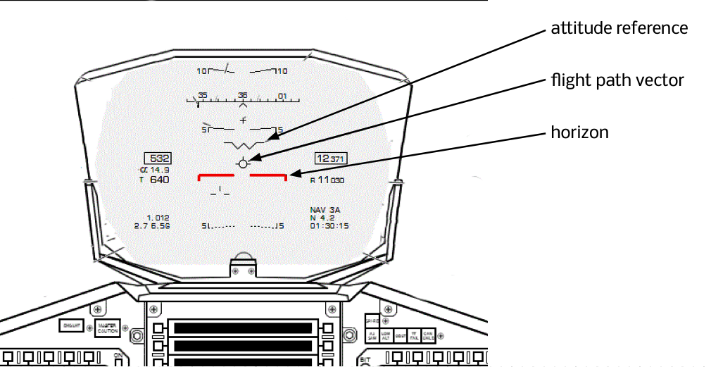
MILITARY pilots (and some business jets) have a cool feature called a head-up display (HUD), which overlays a whole load of flight information like airspeed, an attitude indicator, vertical speed and other things over the view in front of the pilot out of the windshield. One of the neater features of a HUD is that a flight path vector is shown on the attitude display also.
The attitude reference is just like the “dot” in the middle of the mechanical attitude indicator. It tells you which way the airplane is pointing. The flight path vector is more interesting; it tells you which way the airplane is actually moving. And the distance between the flight path vector and the attitude reference is very interesting, because it tells you about your angle of attack.
Determining your angle of attack
Your average single engine piston trainer obviously doesn’t have a sophisticated head-up display, but maybe we can do some imagineering, and construct one in our heads. Let’s try, and see what we can learn.
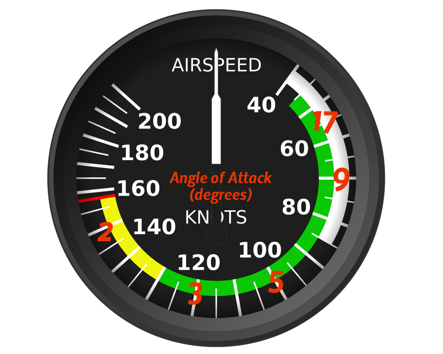
Here’s a typical airspeed indicator, only I’ve annotated the airspeed scale with the angle of attack the aircraft needs at that airspeed. With two basic assumptions (which we’ll discuss) – that the airplane is at it’s maximum permitted gross weight (MGW) and that it’s flying in unaccelerated flight (1.0g) so not turning, and not pulling out of a dive or similar:

We can do this because we know two things:
- a typical wing stalls at 17° angle of attack (at the bottom of the green arc) and
- that from the lift equation, the angle of attack is close to proportional to the reciprocal of the square of the airspeed.
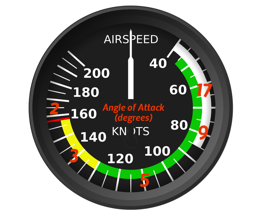
If we were to fly a level turn with 45° of bank we know the g load is 1.41g, and the airplane is developing 41% more lift; the angle of attack for each airspeed has increased by 41%, or, equivalently, the speed at which each angle of attack is maintained is 20% higher. So a new scale of airspeed vs. angle of attack would look like this:
What’s happened is that the numbers have slid around the scale: the airspeed at which maintaining level flight requires flight at the edge of the stall (about 17° angle of attack) has increased from 45 to 55 knots, and all the other numbers have moved too.
If we do the same for level flight at 60° of bank, when the g-load is 2.0, we’d see an angle of attack scale like this:
Same idea, only the red numbers representing the AoA for flight at each of those airspeeds has moved further around the dial.
The second assumption is that the aircraft is at its maximum gross weight. If, instead, the airplane is lighter, the angle of attack for any given airspeed is reduced by the same proportion. If the maximum gross weight for an airplane is 2950lbs but on a given flight it weighs 2650lbs then it is 300/2950 = 10% under weight, and the Angle of Attack at any given airspeed would be 10% lower. Most small airplanes don’t tend to fly more than 10 or 20% underweight, by the time you add passengers and fuel, so at the level of accuracy to which we are working here, it’s ok to ignore changes of weight.1
We don’t have a g-meter in most aircraft, but you do get an idea of the g-force at any moment from how you feel – the bigger the grunt-factor in any turn, or manoeuvre, the higher the g. It’s therefore possible to assess your angle of attack at any given time: estimate the g-force, imagine the scale on the air speed indicator, and that gives you a rough idea of your angle of attack at that moment.
Building a flight path vector
Now let’s construct a flight path vector, in our heads.
We’ll begin with the forward vanishing point. Put the airplane in level flight at cruising speed. Identify the point in front of your nose as you sit in your seat in the airplane, a half or one degree above the distant horizon.2
Because we’re in level flight, that represents the flight path vector at this airspeed and attitude. And because the airplane is built to have a level cabin when in cruise3, it also represents the longitudinal axis of the aircraft.
Going back to the airspeed indicator (calibrated in your head for angle of attack), you’ll see the angle of attack is, let’s say, two degrees. So two degrees above the forward vanishing point is the “zero angle of attack” direction.4
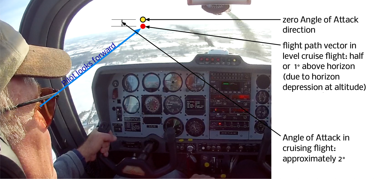
If you keep your head still, you can make a fixed mark5 on the windshield in front of you where that is: the first knuckle of your index finger subtends about four degrees at arm’s length, if you need to know what one, or two degrees looks like: use an appropriate fraction of your knuckle held out in front of you. The point you’re looking for is about one degree above the horizon.
Now you can combine knowledge of your angle of attack (estimated from your airspeed indicator) along with where you know the zero degree angle of attack direction is, to construct a flight path vector in the windshield in front of you. It goes like this:
- Identify the zero Angle of Attack point in the windshield
- Estimate your Angle of attack from your g load and airspeed
- find that point that many degrees under your zero Angle of Attack point
- … and that’s your flight path vector – that’s the direction through the air your airplane is actually moving.
Here are a couple of examples.
Vx climb
In a Vx climb the g load is 1.0, the airspeed is (say) 60 knots, and so the angle of attack is about 9 degrees. We can construct our flight path vector like this:
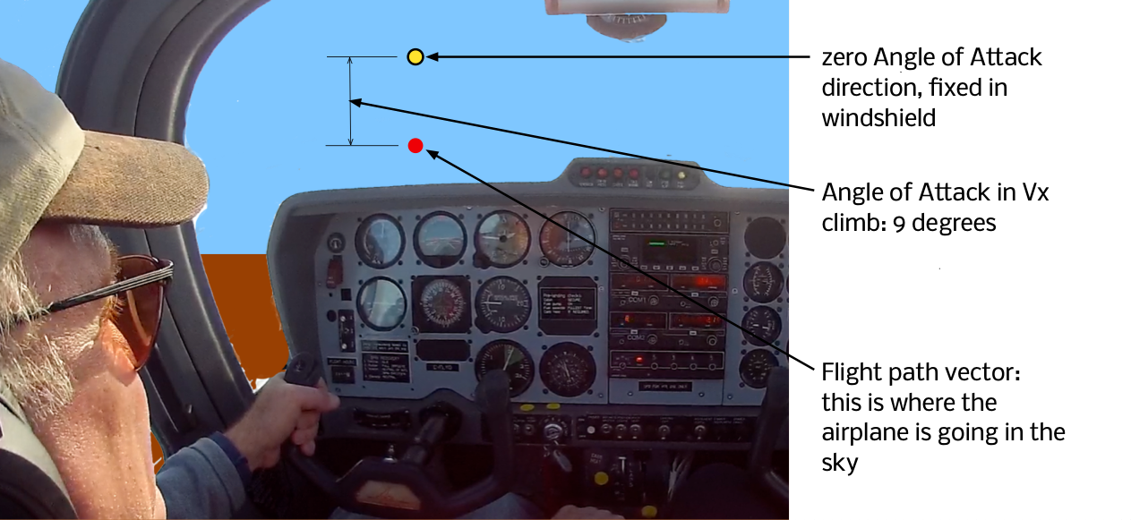
In a Vx climb, the nose is extremely elevated (the zero Angle of Attack direction is way above the horizon), but because the Angle of Attack is high, the flight path vector is a lot lower. You’re not climbing nearly as steeply as you appear to be.
Slow steep turn with level attitude
In this example the airspeed is 70 knots, with the longitudinal axis level with the horizon and the wings are in a 60° bank. We know the Angle of Attack in such a bank at 70 knots must be about 13°, so the flight path vector is constructed like this:
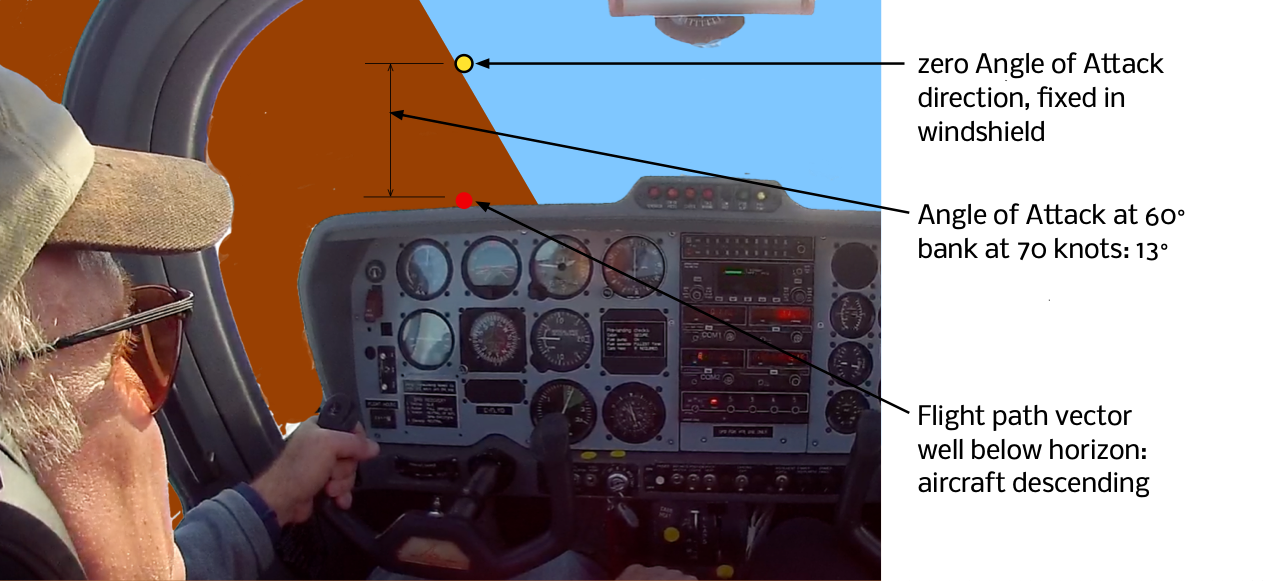
The flight path vector is significantly below the horizon due to the high angle of attack, despite the level pitch attitude. The airplane will be in a descent at this attitude.
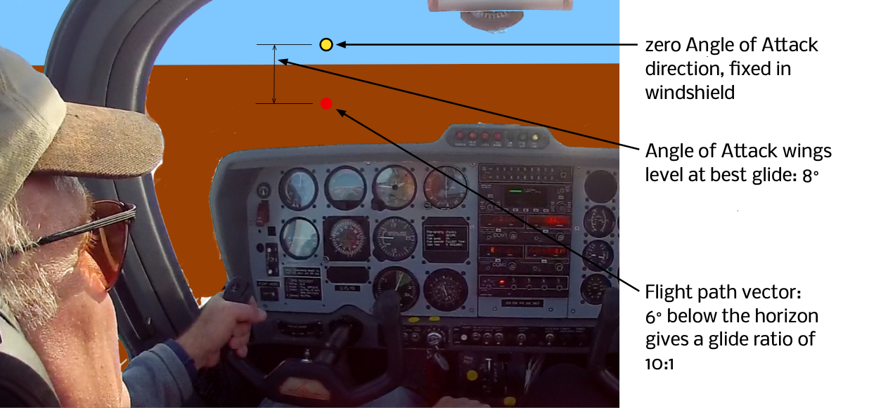
Attitude for “best glide”
Here’s a final example. Have you ever wondered why the pitch attitude for a optimal glide (power off descent) is so similar to the attitude under power at cruise airspeeds? Let’s look at the flight path vector for a glide descent at best lift-to-drag ratio. A small training aircraft typically has a glide performance of about 10:1 – it descends 1 foot for every 10 feet of forward progress. That corresponds to an angle of descent of 6°. Equivalently, the flight path vector sits six degrees below the horizon. Meanwhile, best lift to drag ratio is typically achieved at an angle of attack of about 8 degrees. That means the zero angle of attack direction is about two degrees above the horizon, which is about the same place it sits in cruising flight. So the airplane attitude is the same.
- There should also be a correction for position of the centre of gravity – but the difference that makes is very small, and we overlook it here.
- for the reason why it should be above, and not on, the horizon, see this post.
- The wings are attached at just the right angle of incidence to make this so.
- I’m using the convention that angle of attack is defined as zero when the lift is zero: some texts call this the effective angle of attack.
- with a dry-wipe pen, or a sticker, or something similarly non-permanent